In recent years, the concept of "pattern"
seems to be have caught the imagination of many in the information
technology (IT) industry. This concept was developed
extensively by C. Alexander, first in his seminal book "Notes on
the Synthesis of Form", and then later in "The Timeless Way
of Building" and "A Pattern Language". In these
he describes a set of patterns at various levels which together
constitute a "language" which may be used to design spaces
for living in - from houses up to cities. This language is not
a linear language of sounds or text, but a way of visualizing and
describing relationships within this domain. This work has
inspired many people in the IT industry, including the author of this
paper, to hope that we could develop something similar to Alexander's
work in our industry. It has been clear for years that the
disciplines of architecture in the IT industry leave much to be
desired - in fact, there is a well known quotation current in the IT
industry: "If builders built buildings like programmers wrote
software, then the first woodpecker to come around would destroy
civilization". So, in spite of Alexander's critiques of
the current state of the art of designing and constructing buildings,
it is clear that they are decades, if not centuries, ahead of where
we are currently in computer application development.
Here is a quote from the 1994 book by the author of this paper, "Flow-Based Programming" (ISBN 0-442-01771-5):
It is a truism that most businesses in the Western world would stop functioning if it were not for the efforts of tens of thousands, if not hundreds of thousands, of application programmers. These people are practising a craft which most of the population does not understand, and would not be willing to do if it did. The archetypal programmer is viewed as a brilliant but impractical individual who has a better rapport with computers than with people, slaving long hours at a terminal which is at the very least damaging to his or her eyesight. In fact, of course, the programmer is the key interface between his clients, who speak the language of business, and the computer and its systems, which speak the language of electrons. .... Only if we can narrow the gap between the world of users and that of application developers, can we produce applications which fit the needs of users and do it in a timely and cost-effective manner.
The significant fact ... is that application programming in its present form really is hard and in fact has not progressed all that much since the days of the first computers. This lack of progress is certainly not due to any shortage of advocates of this or that shiny new tool, but very few of these wonder products have delivered what was promised. ... The kind of programming most of us do has its roots in the procedural programming that arose during the 40's and 50's: this new invention called a computer filled a growing need for repetitive, mainly mathematical calculations, such as tide tables, ballistics and census calculations. In these areas, computers were wildly successful. However, even then, some of the experts in this new world of computing were starting to question whether procedural application programming was really appropriate for building business applications. The combination of more and more complex systems, the sheer difficulty of the medium programmers work in and the need for businesses to reduce overhead is resulting in more and more pressure on today's programming professionals.
Flow-Based Programming (FBP) is a technology that
addresses these fundamental problems by breaking away from the purely
sequential, von Neumann architectural style. In FBP, an
application is composed of asynchronously running components,
sometimes called "sequential processes", communicating via
streams of structured data objects called "information packets"
(IPs). The connections between the processes are defined
externally to the processes in the form of a network, and it is this
list of connections and processes that essentially defines the
application. It has been found that this architecture
facilitates communication between users, developers and other roles
in the development of business applications. Some of the
reasons for this will hopefully become apparent in the body of this
paper.
When the connections that define an FBP application are
converted to diagrammatic form, interesting visual structures
emerge. Humans have a well-developed pattern recognition
ability that in fact has helped us to survive for thousands of
years. This skill is what enabled us to detect a tiger lurking
in the jungle undergrowth, or recognize someone as belonging to a
friendly or hostile tribe. Computer application development
tools up to now have not had the kind of visual orientation
which would allow us to take advantages of our natural skills.
In FBP, these patterns are easily recognized, and in fact can be
consciously manipulated at different levels.
In this paper, we will give examples of some of the visual patterns that are found in FBP. This is only a subset, but our intent is to show how certain FBP patterns have characteristic visual shapes, and can in turn be used as building blocks in increasingly complex applications. The paper will close with a description of one of Alexander's more compelling analogies, and a description of some of the lessons that can be drawn from it.
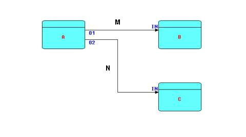
Before continuing further, it is necessary to describe the major elements of FBP. The following diagram is a network or network fragment which should suffice to explain some of the main elements of FBP.
Diagram 1
A, B and C are processors (threads) executing code components. These components are also often referred to as "coroutines", or "processes". In this paper, we will use the term "processor", taken from the 1994 article on the Visual Software Technique Approach (Vista) by Schiffer and Fröhlich. A "processor" may be thought of as an object with a separate thread of control and communication mechanisms. More than one processor can execute the same code, as FBP requires code to be read-only. Every processor, even when executing the same code as another processor, must have its own set of working storage, control blocks, etc. The code executed by one (or more) processors will often be referred to as a "component", reflecting the fact that it acts as a "black box", and can be used in an application without any knowledge of its internals.
Processors are connected by bounded buffers called "connections", across which travel structured chunks of data, called information packets (IPs), as stated above. The component code references a connection by a "port name", and the same port name is used in a definition of which processors are connected to which connections, e.g. "port A of processor X is connected to port B of processor Y".
In the above diagram, O1, O2, and the two INs are ports connecting the connections M and N to their respective processes. Whether or not two processors share code, B and C are free to use the same port names, as port names only have meaning within the components referencing them (and at the network level, of course).
M and N are bounded buffers with a fixed capacity in terms of the number of IPs that they can hold at any point in time. IP size is totally variable from 0 bytes up to the hardware limit. Restricting a connection to a limited number of IPs means that a process may become suspended while sending (if the connection fills up), as well as while receiving (when the connection becomes empty). This allows an application to process a very large number of IPs using a finite (and controllable) amount of storage. It has also been shown that this prevents a problem known as "livelock", and guarantees that all data will be processed. It should be stressed that the bounded buffer connections connecting processor ports are the only way these processors are allowed to communicate with each other.
In Linda, a somewhat similar system described by Gelernter and Carriero in a number of papers, data chunks, known as "tuples" are allocated in "tuple space". For similar reasons, in FBP, IPs are allocated in "IP space", and it is their "handles" that travel across the connections between the processors. Each IP has a definite lifetime, and takes up resources in the IP space, so it acts much more like a real life object (an office memo, say) than like the storage slots in a von Neumann machine. The feeling that data IPs are tangible objects that have to be accounted for is the reason why implementations of FBP have never supported, nor felt the need for, garbage collection.
Any node in the network can be replaced by a subnet (a
partial network with "sticky" connections) or vice versa.
Messrs. Schiffer and Fröhlich refer to such a subnet as a
"compound processor", and point out that, like the overall
network, such a compound processor could easily be built visually.
This concept allows stepwise design where the overall design is
mapped out at a high level, and then the various processors are
"exploded" to lower levels of detail until the developer
reaches the level where processors either have to be built using a
component-level programming language or obtained from a library of
precoded, pretested, components.
Because components can be
recombined in countless different patterns by just changing the
connections, and without any modification of their internals, FBP as
a whole exhibits what the distinguished IBM engineer, N.P. Edwards,
has termed "configurable modularity", which he says is a
characteristic of any system that may be said to be "engineered".
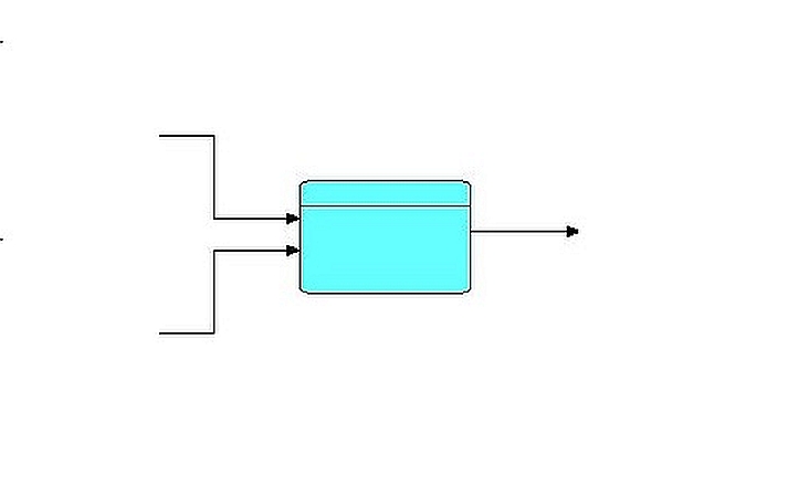
This group of patterns comprises Collate, Merge and Compare patterns, and can be recognized visually as a Y-shape with the stem on the right-hand side. Schematically:
A commonly used FBP component of this type called "Collate" has proven extremely useful when implementing batch update applications in FBP. Like all FBP components, it is a "black box" piece of code, which merges two or more data streams and generates a merged stream, based on alphanumeric keys in the incoming data items. Not surprisingly, there is a close analogy with the punched card "collator" used in the days of unit record accounting machines, whose basic function is the same: merge two streams of data based on one or more alphameric keys. However, since FBP processors are software, rather than hardware, we can generalize the old "collate" function to any number from one to a large number of input streams, and also generalize the key structure to have multiple, hierarchically related, keys. Because Collate works with keys, it is a very natural extension to have it also insert additional group-indicating information packets into the output stream based on the hierarchy of keys. This relieves downstream processors of the need to check control fields to determine when a grouping changes. We will describe this in more detail below.
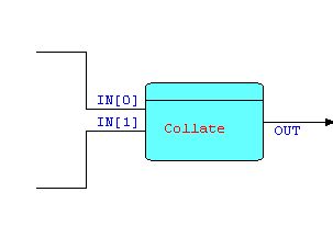
The "Collate" component receives its input streams via what FBP refers to as an "array port", so we can represent the two-stream case as follows:
Diagram 3
The "[0]" and "[1]" indicate that "Collate"'s port "IN" is an array port with 2 elements. Clearly this can be generalized to any number of elements, from 1 upwards.
When we compare the Collate component with the situation in conventional programming, we find that, in conventional programming, batch update programs, in spite of their frequency, are hard to code and harder still to modify, and yet the only assistance programmers have ever received to help them is a diagram (not code) showing the basic logic for Updates, comprised of a complex pattern of moves and compares, and a multiplicity of switches, usually called the "Balance Line" technique. However, it is still only a description of an approach: to adapt it to a particular application you have to massively modify the logic, and then code it up in the language of your choice. If you have more than a small number of input files and control breaks, this can become extremely difficult. In comparison, the FBP Collate processor is a "black box" which can be clearly visualized and integrated with the surrounding logic. It never has to be modified, and in fact, it can be used without any knowledge of how it works on the inside. This is true "information hiding". Merging 'n' input streams is just as transparent and easy to visualize as merging two.
As mentioned above, a natural extension of the Collate logic is to have the component inject "signal IPs" into the output stream to indicate hierarchically related groupings. In hindsight, it turns out that a lot of the Balance Line's complexity is due to the fact that much of the logic occurs when control fields change their values. In FBP, this logic will be in a downstream processor, and will be driven by the arrival of explicit signal IPs generated by the Collate.
In earlier FBP implementations, these signals marked the end of each group (frequently nested), and had a level number to indicate the hierarchical level. Later however, it was realized that a more general mechanism was to use "bracket IPs": these can be nested very naturally to represent a hierarchy of groupings, and do not require a level number. A stream of this type is then homologous with an acyclic tree, and in fact it is often useful in FBP to convert from a stream to a tree or the reverse. In FBP, we allow an IP to be the base of an acyclic tree of IPs, and these "tree IPs" can be intermixed freely with regular IPs in the streams of data passing between processors.
Let us show a small example. Suppose we are collating two streams of information packets - call them "master records" and "detail records". Let the master records have key values of 1, 2 and 3, and the detail records key values of 11, 12, 21, 31, 32, 33 and 41, where the first digit corresponds to the master key values. Collate will then generate a sequence as follows (without group indicators):
m1 d11 d12 m2 d21 m3 d31 d32 d33 d41
If group indicators are requested, the output will now look like this (we can use bracket characters to represent "bracket" IPs):
( m1 d11 d12 ) ( m2 d21 ) ( m3 d31 d32 d33 ) (d41)
You will notice that the last group has no "master" - this can readily be recognized by the fact that a bracket is immediately followed by a detail. This will typically happen if the detail IP is an "add" function. Clearly the logic of all downstream processors is significantly simplified, as they no longer have to compare key values to determine when groupings change.
In most business applications, one will have a hierarchy of groupings, e.g. country, state, city. The start of a grouping is often also indicated by an IP of a particular type, but does not have to be. The end of the grouping is usually the signal to output totals, and perhaps "roll" them up to the next higher level.
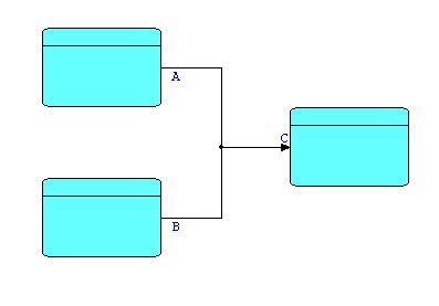
The right-pointing Y-shape does not actually have to have a component at the point of joining, as FBP supports 'n' ports feeding one port (although not the converse). With 'n' ports feeding one port, IPs arriving from the different upstream ports are merged on a first-come, first-served basis. Schematically:
Diagram 4
The black dot indicates the merge relationship. If two lines cross without such a mark, they are independent.
IPs being sent from the two upstream ports, A and B, will arrive interleaved. The IPs sent out by a single upstream process will still arrive in the correct sequence, but their sequencing relative to the output of the other process will be unpredictable. In spite of this unpredictability, this function turns out to be useful surprisingly often. The downstream processor might be a Sort, so the sequence of its incoming IPs is going to be changed anyway; the IPs from the two output streams may be easily distinguishable, so we can always separate them out later; or the downstream processor may need to receive its input data as fast as possible - any additional sequencing may cause delays, and in fact may even cause deadlocks, which we will talk about below.
Finally, within the group of components of the same general shape, we may wish to create custom "merge-type" processors to combine two or more streams of data according to various other criteria: e.g. round-robin, concatenate (all of one stream followed by all of another), test-based (e.g. merge each IP from one stream after an IP in the other stream containing some characteristic data). Many of these could be generalized by the addition of parameters, and therefore could be available off the shelf.
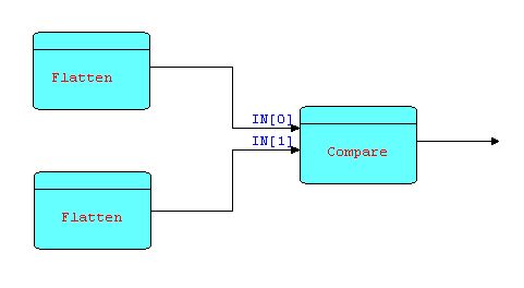
One other group of patterns of the same general shape are "compare" components. We will show one example only - the "same fringe problem". This involves testing whether two binary trees have exactly the same fringe (sequence of leaves). This problem is almost impossible to code without using coroutines, or some equivalent mechanism. Here is a simple FBP solution:
Diagram 5
where each instance of FLATTEN walks a tree and
sends out an information packet for each leaf. COMPARE reads
pairs of leaves, one from each input port, compares them and
terminates with some kind of error message if a pair doesn't match;
otherwise COMPARE continues until all input information packet pairs
have been received and processed.
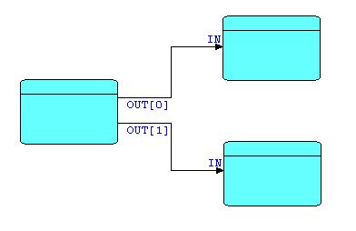
Not surprisingly, the Y-shaped components described above have their inverse: the Y-shape with the stem on the left, e.g.
Diagram 6
This type of pattern represents a class of processors that either split or replicate the incoming stream. In FBP this is usually indicated by the name of the component, e.g. Select, Split, Divide, on the one hand, or Replicate, Copy, etc. on the other, rather than by any difference in icons. Up until now, the graphical support for FBP implementations has been relatively unsophisticated, but a potentially interesting future direction would be to use different icons for the broad classifications of components, along the lines of the icons typically used for analogue computing notations.
The left-pointing and right-pointing "Y" shapes shown above together form a pattern at a still higher level: that of complementary component pairs. Other examples are Read/Write, Expand/Contract, Decompose/Recompose, etc. The following example uses two (nested) pairs of complementary components. The problem described seems very simple as described in words, but in fact is quite hard to do using conventional (synchronous) coding.
The task, called the "Telegram Problem", originally described by Peter Naur, is to write a program which accepts lines of text and generates output lines of a different length, without splitting any of the words in the text (we assume no word is longer than the size of the output lines).
In FBP, the problem description itself suggests the patterns a developer would use, as follows:
"words" are mentioned explicitly in the description of the problem, so it is reasonable for the designer to treat words as information packets (IPs) somewhere in the implementation of the problem. It would actually be counter-intuitive to deliberately avoid turning words into IPs, given the problem description
there is no "main line" in FBP, so the programmer is not tempted to force a subpattern of the solution to be "top program", which almost inevitably happens in conventional programming.
We have established that we should have IPs represent words somewhere in the application. We will also need a Read Sequential component on the left of the network, reading input records from a file, and a Write Sequential component writing the new records onto an output file. Here is a partial network:
Diagram 7
Now the output of Read Sequential and the input of
Write Sequential both consist of streams of IPs (records) containing
words and blank space, so it seems reasonable that we need, at
minimum, a component to decompose records into words and a matching
one to recompose words back into records. Given the problem as
defined, the diagram below seems to be a complete description of the
problem solution, in fact involving a total of 4 (reusable)
components. Let us add our two new components into the
picture:
Diagram 8
Now we have another matched pair of
components - shown in the diagram as DeCompose and ReCompose.
Given that these components are true black boxes, it will usually be necessary to specify some parameters to provide information that they don't have. For example, the Write Sequential and Recompose components will have to know what size records to create - this can be read from a file descriptor, or from a parameter specified with the network definition. In the most recent versions of FBP we introduced the concept of Initial Information Packets (IIPs). These are special FBP read-only constructs defined along with the list of connections, and connected to ports. When a processor does a "receive" from this port, a "normal" IP is created using the contents of the IIP, and is from then on processed just like a normal IP. An additional "receive" within the same activation will return an "end of stream" condition. IIPs are typically used for the file designations or path information used by the occurrences of the Read Sequential and Write Sequential components.
More generally, the amount of parameters on a processor may range from none (when there is no variability in the component's function) to medium, as in the case of utilities, such as a Sort component, to what can really amount to a problem-oriented mini-language, perhaps executed by a single-threaded interpreter "black box". In fact, FBP allows many languages at many different levels of expressiveness to coexist in a single application, so no one language is forced to support all possible uses.
Although we now have a number of complementary pairs of useful components, of course any individual component can still be used separately. Suppose we simply want to count the number of words in a piece of text. Another general class of component is that of "reference" components, where the original input IPs are passed through unchanged, while some derived information is sent out via another output port. An example of such a "reference" component is Count, which accepts IPs, and forwards the incoming IPs at one port (if it is connected), and a count IP at another port at end-of-stream time. The resulting structure might then look something like this, with Count's first output port unconnected ("reference" components are typically written so that, if the first output port is unconnected, the IPs are dropped - alternatively their output could be routed to a Discard processor):
Diagram 9
We can keep on adding or changing processes indefinitely, and yet the mental model stays very natural and straight-forward. We will use a variant of this diagram in the next section.
The following patterns are, respectively, a situation that can occur in many asynchronous systems, characterized by a recognizable visual pattern, and another, equally visual, pattern that can be used to resolve this problem.
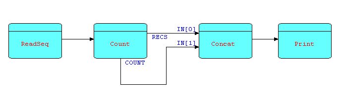
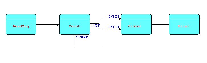
Suppose the requirement is to count a stream of IPs, printing them out on a report, followed by the count. We will suggest the Count processor described above, but in this case with the first output port (for forwarding input IPs) connected. The IPs being sent from this port will be combined with the count IP using a Concatenate processor, mentioned above: it accepts and outputs all the IPs from its first input port, followed by all the IPs from the second, and so on.
Diagram 10
Suppose now the requirement is changed, and we wish to position the count in front of the IPs being counted. It would seem a natural step to change the picture as follows:
Diagram 11
If we were to implement this exactly as shown, we would find that the application very quickly reaches a state where no processor can proceed - this is a classic example of what is known as a "deadlock", and is due to the fact that the connections do not have infinite capacity. In fact, if they did, we could not guarantee that the application would ever terminate, which would not be a very desirable characteristic. The use of bounded buffer connections is what allow an FBP application to process large amounts of data using finite amounts of resources.
The reason for the deadlock is that the count IP is not generated until the Count processor closes down, but Concat is waiting for that IP, so the IPs being generated ahead of the count will accumulate in the connection linking OUT to IN[1]. Since all connections are bounded buffers, when this connection fills up, COUNT will be suspended. In the pattern shown above, clearly COUNT will never be able to process all of its input IPs, so it will not be able to close the OUT connection, which is the signal for CONCAT to switch to receiving from OUT[1]. CONCAT will remain suspended waiting for data on a port that will never receive data; and COUNT is suspended trying to send to a connection that will never be offloaded. This is an FBP version of the "deadly embrace". It is however a design problem, and can always be resolved by a minor design modification involving yet another pattern: the "infinite queue".
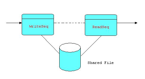
The term "infinite queue" may be a slight misnomer: it is merely very large, as it is normally implemented by a sequential file on disk. And "queue" is an earlier term for an FBP bounded buffer connection. In implementations of FBP the "infinite queue" is usually implemented as a Writer/Reader pair referencing a shared file, where the Reader is held back from starting until the Writer has completed. Using a dotted arrow to represent this kind of interlock, we can show it as follows:
Diagram 12
In this diagram, the dotted line does not indicate a connection carrying application data, but rather a signal (a "trivial" information packet) automatically generated when the Writer closes down, which can then be used to prevent the Reader from starting until its arrival.
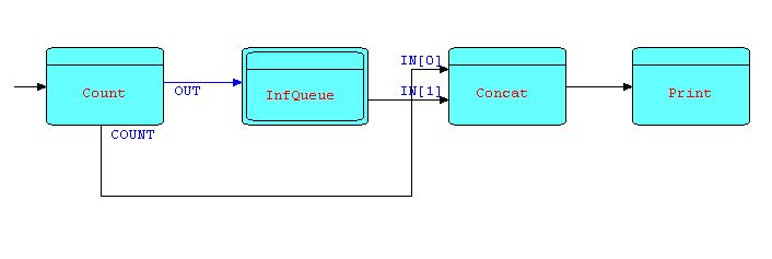
To improve legibility, we will represent this pattern by a compound processor (a subnet) - call it INFQUEUE. We can now solve the deadlock shown in Diagram 11 by inserting an INFQUEUE between COUNT's first output port and CONCAT's second input port - as follows:
Diagram 13
In the diagramming tool we use, INFQUEUE is shown
with a double border to indicate that it is a "compound
processor". Double-clicking on this kind of processor
allows the user to "drill down" to the next level.
The IPs coming out of COUNT's first output port will then be held in the "infinite queue" until CONCAT is ready to start receiving them. You can have as many instances of INFQUEUE in a network as you want, provided of course that they use different shared files.
It should be noted that the "cross-over" network topology of the deadlock shown above is itself a recognizable pattern (an antipattern?). It is one of a number of network topologies that visually signal to the FBP programmer the possibility of a deadlock, and can be described as a "divergent-convergent" visual pattern. It only signals the possibility - the designer will still have to think it through. Notice that diagram 10 did not result in a deadlock, even though it was "divergent-convergent", but diagram 11 did.
In batch system environments, such as IBM's MVS, where batch jobs are divided up into job steps, these shared files are of course the way the the steps of a job communicate. This suggests that a batch job can be laid out as a large FBP network, and then split up into job steps by replacing connections by Write/Read pairs referencing a shared file - each such pair being in effect the pattern shown in diagram 12. More generally this applies anywhere two processes cannot share high-speed memory, e.g. between separate virtual machines, separate transactions, or even two copies of the same batch job running on successive days.
In conventional programming, Sort programs are usually packaged as stand-alone utilities, although various exits (callbacks) are provided to allow its behaviour to be modified. In conventional programming, when the designer wishes to add application-specific function, the Sort has to be the main line, and all the other program logic has to be crammed into the exits. Furthermore, since the exits are subroutines, they cannot "remember" anything from one invocation to another unless this is placed in "static" storage, resulting in non-reentrant code - i.e. using side effects. In the first implementation of FBP, we parameterized the standard IBM batch Sort by building an input exit which could receive IPs, and an output exit which could send them. The standard IBM batch Sort thus became a stream-to-stream Sort. Basically all the upstream processors in the network multithread with the input exit, and all the downstream processors multithread with the output exit. We could of course have used a hand-coded Sort processor, or indeed a whole set of different ones, but the standard IBM Sort has decades of research behind it, and provides exits which could be modified as just described. Furthermore, the exit interface provided by the IBM Sort has become a standard interface for Sort programs provided by other vendors.
When Sort is packaged as a stream-to-stream processor some interesting advantages start showing up, for instance:
performance: a Sort which is run as a separate job step has to use files for its input and output. If we provide Sort as a stream-to-stream component, then data IPs which are to be sorted no longer have to be written to a file first (and do not have to be retrieved from a file afterwards), but can simply be sent across a connection to the Sort, which in turn sends them on to the next process when it is finished, resulting in a considerable savings in I/O overhead. Actually, the "central" Sort phase (when the Sort is working with its internal files) is the only part of the Sort which cannot be overlapped with other processes when using non-preemptive scheduling software. Using preemptive software, even that phase can be overlapped with independent processes.
flexibility of positioning control fields: if the control fields are not in a standard place for all the input IPs, you can simply insert a transform process upstream of the Sort to make the key fields line up, or even build them dynamically from other formats.
eliminating unnecessary sorting: sometimes, some of the IPs are known to be already sorted, in which case they can bypass the Sort, and be recombined with the sorted IPs later. This is not practical when the Sort is a separate job step.
improved sorting techniques: if you know something about the characteristics of your keys, you may be able to build more complex networks which perform better than a straight Sort. For instance, if you are sorting on a name field, it might make sense to split the data 26 ways, sort each stream independently, then merge them back together - this might give improved performance over a conventional Sort. A good rule of thumb is that the running time of most Sorts is proportional to n.logn, where 'n' is the number of records. Since this is a nonlinear relationship, it may be more efficient to split the Sort into several separate ones. The Sort process can thus be implemented with other components or subnets for purposes of experimentation.
multiple instances of the Sort processor may run asynchronously within a single network. In conventional programming, these either have to run in separate programs, or somehow have to be combined into a single Sort process.
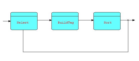
Here is a picture of a Sort processor with some IPs going around it, and with Sort tags being generated on the fly by an upstream processor (BuildTag):
Diagram 14
Note that the data
bypassing the Sort will arrive ahead of (most of) the Sort's output.
This data could instead be fed to an infinite queue, where it can
wait until sorted data starts to emerge from the Sort, and then be
merged back into the sorted stream. The designer will have to
decide whether this will perform better than just sorting everything.
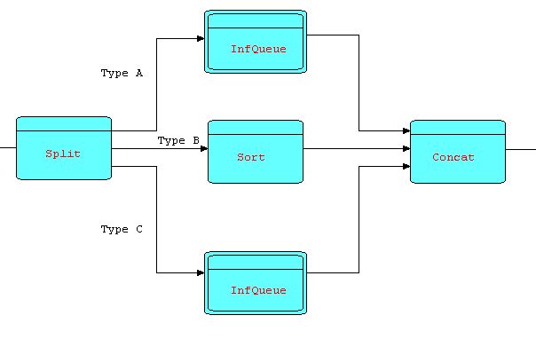
Because the Sort pattern does not start to output any data until all the incoming data has been received, there is the potential for deadlocks. However, as before, these can be prevented by the judicious use of infinite queues. For instance, suppose that the input to the Sort consists of three types of data in sequence: type A is known to be already sorted, type B, which needs to be sorted, followed by type C which again is sorted, and all three types are to be merged based on the same key, then a pattern which conclusively avoids deadlocks might be as follows:
Diagram 15
This will readily be recognized as another
(slightly more complex) instance of the "divergent-convergent"
pattern.
Not surprisingly, the Sort described above turns out to be the precursor of a whole class of Sort components, e.g. Sorts which process one bracketed substream at a time. In fact, one could visualize a number of resequencing components with various characteristics, which all fit into the niche described above.
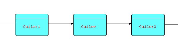
Consider the following diagram:
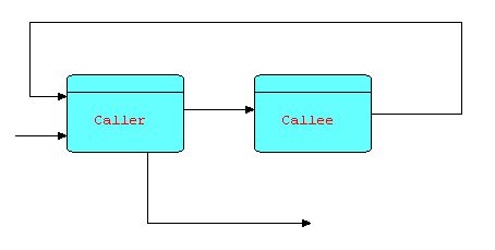
Diagram 16
Suppose that CALLER sends information packets to CALLEE to request that it return some data. Each time CALLEE receives a request, it processes it and sends the result (or results) back to CALLER, after which it returns to waiting for another request. In fact, the relationship between CALLEE and CALLER is very similar to that of a subroutine to its invoker, in that CALLEE does not execute until an IP arrives at its input port, and CALLER has to wait until the requested data is sent back.
You may wonder what is the advantage of making CALLEE a separate process, instead of simply a subroutine. Firstly, CALLEE can maintain continuity between successive invocations - this is a problem with subroutines or callbacks, which in many languages require some form of non-reentrant code or global data. Secondly, CALLEE can manage a serial resource of some kind - for instance, the requests might be both "retrieve" and "store" requests. This reduces the possibility of contention, or even deadlocks, at some cost in performance. Of course, this is only an option, but one that has often been found useful. Thirdly, a small change to the topology provides much more flexibility. Suppose we make a minor change to the above diagram, based on the idea that the part of CALLER's logic following the "send"/"receive" can usually be split into a separate process downstream of CALLEE:
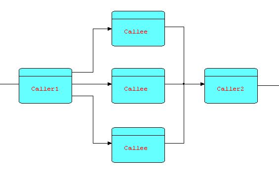
Diagram 17
Now CALLEE can be multiplexed, as in the diagram below:
Diagram 18
You will now recognize this as the combination of two patterns that we have seen earlier, and in fact it is a pattern in its own right. This multiplexing technique can be of significant benefit when CALLEE is I/O-bound, but in today's multiprocessor machines, it can also be of benefit if the function is heavily CPU-bound, as well, as different (software) processors can be assigned to different (hardware) processors.
Thus we see that a send and receive issued by CALLER (in diagram 16) effectively behaves like a "call". However, a small topological change "opens out" the diagram and allows performance improvement by means of multiplexing. A similar point was made by Gelernter and Carriero, describing the Linda system, in which they state:
"In our experience, processes in a parallel program usually don't care what happens to their data, and when they don't, it is more efficient and conceptually more apt [my italics] to use an asynchronous operation like Linda's "out" [FBP "send"] than a synchronous procedure call.... It's trivial, in Linda, [or FBP] to implement a synchronous remote-procedure-call-like operation in terms of "out" and "in" [FBP "send" and "receive"]. There is no reason we know of, however, to base an entire parallel language on this one easily programmed but not crucially important special case."
In the early part of his book "Notes on the Synthesis of Form", Alexander describes the concept of "fit". He makes the point that, as humans, we find it very hard to detect "fit", but are well-adapted to detecting "lack of fit". Think of trying to decide if the edge of a piece of wood is straight: the natural thing to do is to put it against a straight surface and see if any gaps show in between. As we try to improve things by reducing the misfit factors, we soon discover that these factors tend to be interrelated: fixing one may exacerbate another, so there is a continuous process of compromise between a number of less than ideal solutions. Intuitively, the less interrelated the misfit items are, the easier it will be to reach a state of acceptable fit. This means that our only hope of reducing misfit factors is if these factors occur in clusters such that the connections between clusters are relatively loose. In application development, this works best if the infrastructure software components also define boundaries between misfit factors.
To help the reader to visualize this relationship, Alexander imagines a system of 100 lights, where each light represents a misfit factor - "on" for lack of fit, and "off" for fit. Imagine further that a given light that is on always has a 50-50 chance of going off in the next second, and one that is off has a 50-50 chance of going on in the next second, but only if at least one of its neighbours is on. Clearly this linkage allows such a system to eventually reach a condition where all lights are off, but it also ensures that, if they are too densely connected, this may take a very long time! Thus the network of lights symbolically represents the way misfit conditions overlap and interfere with each other. Intuitively we see that, in any network of lights representing a real system, there will be more densely and less densely connected areas, so that a disturbance in the equilibrium of a densely connected area will not lap over into other neighbouring dense areas, or if it does it should damp out quickly. Conversely, if after analyzing a system, you arrive at a network of misfit factors where every factor is linked to every other, you might as well give up the idea of ever wrestling it into a state of equilibrium where every light is off.
Now we can apply this concept to the development life cycle of a computer application. Imagine that we have a first implementation of our computer application, and that we have laboriously arrived at the "off" state (or as close to it as we can get). Now every maintenance activity is going to disturb that equilibrium. In the densely connected situation, maintenance activities will cause widespread disequilibrium, while in the loosely connected situation, only a local area will be affected, and the disturbance will damp out quickly. In practice, when maintaining computer applications, each time the system is modified, this equilibrium becomes progressively harder to reattain, because the application will be maintained by people who are further and further away in time and culture from the people who originally built it, and who presumably had some kind of overarching concept in their minds (usually undocumented!). This process will be improved significantly if the application was built with maintainability in mind, but this is unfortunately not the norm. Here is a quote from "Notes on the Synthesis of Form": "The Mousgoum [a culture in Africa, mostly in the Cameroun - their dome-shaped houses are called tòléks] cannot afford, as we do, to regard maintenance as a nuisance that is best forgotten until it is time to call the local plumber". In fact the Mousgoum do not use disposable scaffolding when building a house, but build it in as part of the structure, so that any part of the house that needs to be maintained is always accessible. It is interesting to note that FBP networks are also intrinsically "instrumentable": display processors can be inserted on any path to view what is going across that path, or individual processors (or groups of them) can be run independently by building "scaffolding" around them. It has often been observed that programming languages and methodologies are usually oriented towards the creation of the original application, rather than its long term maintainability, perhaps because psychologically getting the application working initially is thought of as an end point, rather than as the first step on a long journey. In practice, complex business applications often undergo decades of maintenance (frequently to the surprise of the original developers), done by people who cannot see the whole picture but instead are forced to work on a small piece that they do understand, praying that they have not interfered with the parts they don't. From the foregoing we deduce that maintainability is enhanced if the application can be divided up into areas whose misfit factors are well separated from those of other areas. If this cannot be done cleanly, every change to one area will have unforeseen, and perhaps unforeseeable, effects on other areas. In addition, a developer can concentrate on a particular area with good confidence that he or she is not going to damage areas outside of his or her domain.
Let us take a look at the diagram of dependencies between misfit variables in the section of Alexander's book referenced above. The author puts this diagram in context as follows:
Now let us go back to the question of adaptation. Clearly these misfit variables, being interconnected, cannot adjust independently, one by one. On the other hand, since not all the variables are equally strongly connected (in other words there are not only dependences between variables, but also independences), there will always be subsystems like those circled below, which can, in principle, operate fairly independently.
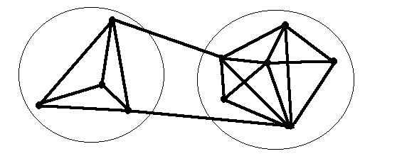
Diagram
19
Alexander goes on to say:
We may therefore picture the process of form-making as the action of a series of subsystems, all interlinked, yet sufficiently free of one another to adjust independently in a feasible amount of time.
In an introductory section in "The Timeless Way of Building" called simply "The Gate", Alexander says:
14. ...we must first learn how to discover patterns which are deep, and capable of generating life.
15. We may then gradually improve these patterns which we share, by testing them against experience: ...
16. ... The structure of the language is created by the network of connections among individual patterns: and the language lives, or not, as a totality, to the degree these patterns form a whole.
17. Then finally, from separate languages for different ... tasks, we can create a larger structure still, a structure of structures, evolving constantly, ... This is the gate.
These two quotations describe exactly what happens in maintaining systems constructed using Flow-Based Programming. They also help to explain why people who have adapted their thinking to the concepts of Flow-Based Programming feel empowered, and often have difficulty in going back to the older technologies. In summary, FBP seems to partake to a large extent of what Alexander calls the "quality without a name".
In the foregoing, we see a new programming paradigm which takes much more advantage of human pattern perception mechanisms than its predecessors. It is not surprising that building applications using long strings of text has not produced particularly maintainable systems, as the mental patterns available during such a design process tend to be high-level and highly abstract.
In Flow-Based Programming we have a significant paradigm shift in the way application development is performed. FBP is visual, pattern-based, and a better match with the way things work in the real world, so it makes better use of human thought processes than does conventional programming. When these concepts are used on a day-to-day basis, and accepted as the basic application development paradigm, rather than as an afterthought on what is fundamentally still a sequential, synchronous way of looking at the programming world, I believe that they have the potential to revolutionize the way applications are constructed and maintained, resulting in applications that are of higher quality, more efficient, more maintainable, and more responsive to user needs.
C. Alexander, "Notes on the Synthesis of Form", Harvard University Press, 1964, ISBN 0-674-62751-2.
C. Alexander, "The Timeless Way of Building", Oxford University Press, 1979, ISBN 0-19-502402-8
C. Alexander, "A Pattern Language", Oxford University Press, 1977, Library of Congress Catalog Card Number 74-22874
N.P. Edwards, "On the Architectural Requirements of an Engineered System", IBM Research Report, RC 6688 (#28797), T.J. Watson Research Center, Yorktown Heights, NY, 8/18/77
D. Gelernter and N. Carriero, "Coordination Languages and their Significance", Communications of the ACM, Vol. 35, No. 2, February 1992
J.P. Morrison, "Flow-Based Programming", van Nostrand Reinhold, 1994, ISBN 0-442-01771-5
S. Schiffer and J.H. Fröhlich, "Vista - a Visual Software Technique Approach", "Visual Object-oriented Programming: Concepts and Environments", Margaret M. Burnett, Adele Goldberg, Ted G. Lewis (ed.), Manning Publications and Prentice Hall, 1995, 199-227
For a more complete bibliography, see the bibliography
in the book "Flow-Based Programming".