Flow-Based Programming - Chap. XXI
General Framework for Interactive Applications
|
This chapter has been excerpted from the book "Flow-Based
Programming: A New Approach to Application Development" (van
Nostrand Reinhold,
1994), by J.Paul Morrison.
To find out more about FBP, click on FBP
. This will also tell you how to order a copy.

For definitions of FBP terms, see Glossary
|
This chapter talks mainly about our experience, pre-1994, using the
FBP implementation called DFDM and IBM's ISPF. More recently, we
built an e-business application using the Java implementation of FBP
[now
called JavaFBP]. This was also essentially a loop-shaped network,
but
running across multiple servers (other chapters in my book talk about
the
ease of distributing FBP applications across physical networks).
Communication between the user and the servers was handled by IBM's
MQSeries
transporting XML messages. The application also needed to communicate
with
multiple "back-ends", which it did using either MQSeries or CORBA.
Material from book starts here:
In this chapter I am going to describe a general framework for
interactive
applications, showing a general structure and some component types
which
could help in the design of such applications.
We will start by reproducing Figure 19.3, which shows an IP
substream
travelling from application logic to a screen manager process and back
again, and showing how it can be fleshed out to produce a very general
design for interactive applications. You will remember the following
diagram:
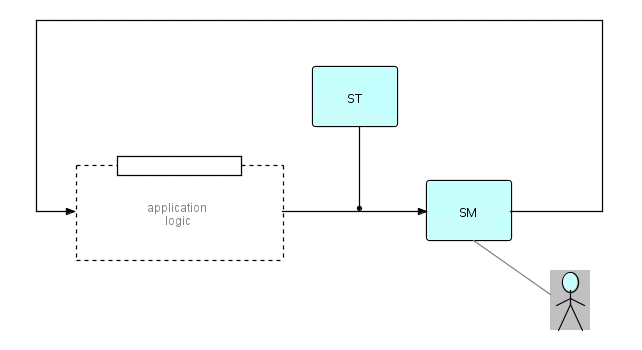
where SM  is a Screen Manager
      ST  starts the network as a whole
      the dotted line represents logic processes

Figure 21.1
You will remember that in IMS we had to split the process marked SM
into
SI and SO (Screen Input and Screen Output respectively), and change the
function of the "return connection". However, for now, we will work
with
the above diagram, bearing in mind that it is very easy to convert it
into
one which will run in the IMS/DC environment.
In what follows I will describe a system we built using a single
generalized
Screen Manager component (which I will refer to as ISM1 - ISPF Screen
Manager
1) which used IBM's ISPF both to write to and read from a terminal, but
the concepts are extremely general and can be applied to other screen
management
software.
Although some systems allow a screen to be generated without using a
program, it is simpler to assume that every application starts by
putting
up a "What do you want to do?" type screen. So assume that ST causes SM
to output a menu screen. SM will have to have a place where the user's
answer can be stored, so we can assume that ST sends out a substream
consisting
of at least three IPs: open bracket, "request" IP, zero or more data
IPs
and close bracket. The brackets are needed so we can have a variable
number
of data IPs in the substream. The request IP will have, among other
data,
the name of the screen to be displayed. This substream then arrives at
ISM1, which puts up a menu; the user enters a choice; the substream
goes
through the processing logic (which may change the contents of the IPs,
or even add or remove IPs from the substream); and eventually we get
back
to ISM1 which puts up a new menu.
Now let's look a bit more closely at ISM1. This component accepted
an
input substream, put any variable data into position on the screen
using
the data descriptors associated with the data, and waited for action on
the part of the user. When that occurred, the modified data was placed
back into the right places in the data IPs, and the substream was then
sent on to the next process downstream. ISPF identifies fields on the
screen
by name, and ISM1 used the field names from the descriptor to determine
where to put each variable field.
In addition to this substream, referred to as the "fixed substream",
ISM1 also accepted an additional, optional substream, called the
"repeating
substream". The mental image supported was that the screen has a fixed
part, normally describing one or a small number of individual entities,
and an optional list. Thus we could show a person's family on the
screen:
his or her personal information, the spouse's information (a separate
IP),
these providing fairly complete information, and zero or more children,
showing just name, age and gender, say. If the user wanted more
information
on a child, he or she could select the child, and get a full screen
devoted
to that child, which might have further lists, e.g. education. One of
the
really neat things about being able to use IPs in this way is that both
the list of children and the full screen describing a single child can
be driven by the same IP - we just decide how much information we are
going
to show from that IP. By the way, since each screen was built using two
substreams, we bracketed them together so that ISM1 would think of them
as a unit - so ISM1 was using a substream of substreams.
Because field names are not unique in the repeating part of the
screen,
we could not use ISPF field names to control this part of the display,
so we used a run-time table describing which fields from each IP went
where
in the repeating section. This had some interesting capabilities - ISM1
allowed you to specify more than 1 line per repeating IP, and the
developer
could also specify whether a "select" column (simulating the 1-byte
column
ISPF provides for selecting one or more items from a list) was required
or not.
ISM1 also used the dynamic attributes which we talked about in
Chapter
11 to keep track of which fields had been modified, and which were
null.
As I mentioned in that chapter, ISM1 also provided a special display
for
fields which had been "tagged" with error codes, and would let the user
step through these errors using a reserved function key. ISM1 actually
would not allow the user to go on to the next screen until all these
"tags"
had been removed one way or another! There has been lots of debate
about
whether this is a good idea or whether systems should be more
forgiving!
However, the important thing to remember is I am talking about the
design
of a single component - this in no way affects or is affected by the
basic
architecture of FBP.
So far, ISM1's abilities might seem about what you would need if you
were "black boxing" a display function. However, it also provided
another
capability, which dramatically simplified the logic in the other
components
of the application: we have discussed this in Chapter 11 under the
title
of "representations". As I said in that chapter, representations mainly
come into play when you need to present data to humans, or port it
across
systems.
In a prototype of an interactive application using straight ISPF I
found
three PL/I fields had to be defined for every numeric field on the
screen:
-
the field in a computational format
-
a zoned decimal field (e.g. 000001234)
-
a character field for input in case the user wanted to modify
the field
When we converted this prototype to use ISM1, the number of fields
we had
to declare in the HLL portion of the application dropped by 2/3! We
also
discovered a number of additional bonuses:
-
you could send an IP with an attached descriptor to ISM1 and it
would automatically
be displayed in the desired format
-
the user could enter the data in free-form, but you could be
sure that
it wouldn't get into the system unless it was a valid representation
-
you could implement a standard input convention for your whole
shop - e.g.
require that the field be clear apart from the incoming data (some
screen
managers allow you to leave junk at the end of a field following the
data
just entered)
-
you could send an IP to ISM1 for interactive handling, or you
could send
it to a file writer and you didn't need to make any changes to your
data
IPs. The effect of this was enormously improved testing and regression
testing, because you could test a lot of your logic in batch.
On one project in IBM Canada, this last technique was used very
effectively
by my colleague, Philip Ewing. Later in this chapter I will share with
you what he has written about that project.
We have now sketched out a screen management component ISM1, which
accepts
one or two substreams as input, and outputs them again after the user
has
responded. If you are working in the IMS/DC environment, it wouldn't be
all that hard to split these functions and link them together using
persistent
storage.
Now let's look at the first figure in this chapter. We need to fill
in the logic between SM and the application logic. To do this, the
first
step is to interpret the user's action. Restricting ourselves for
simplicity
to ISPF and 3270-type terminals, the user may decide to:
-
modify any data field, including Select fields as a special case
-
enter a command in the command area
-
hit a function key
-
hit a Program Attention key (this will lose modified data)
-
hit Attention
-
position the screen cursor to a particular field
These will of course often be combined, e.g. putting an M [for
"maximum"]
in the command line and hitting PF8 ["down"] causes a jump to the
bottom
of the data in ISPF.
All these actions have to be encoded so that downstream processes
can
decide what is the appropriate response. If we add in more modern
devices
and interfaces, obviously there are still more variations, e.g.
monitoring
key-strokes and mouse movements in real time, but it seems that we will
still have the cycle (or maybe many concurrent ones) of display - user
action - interpret user response - program action - display.
In the ISPF world, and also IMS/DC, function keys are usually
treated
as commands, so one of the standard outputs of our Screen Manager will
be a "command". These may be the very frequent ones like UP, DOWN, END
and HELP, which are almost universal, or more application-specific
ones.
It turns out that these commands are convenient bases for the decision
about what to do next. Always remember that each of the components
described
here can be used independently of any other. Now, in Chapter 7 we
described
DFDM's dynamic subnets - subnets which were linked as separate load
modules
and were loaded in dynamically and given control by a special component
called the Subnet Manager. This will provide a convenient way of
subdividing
and managing our application. The Subnet Manager is driven by IPs
containing
dynamic subnet names, so we need a component which will take the output
of the Screen Manager and generate the subnet names for the Subnet
Manager.
Let's call this the User Response Analyzer (URA).
The URA component's job is to look up in a table patterns consisting
of screen + action, screen only or action only, and decide what to do
about
them. As we said, since it sits upstream of the Subnet Manager, its
main
job is to select subnet names to be sent to the Subnet Manager, but you
might decide to have it bypass the Subnet Manager, and send its input
IPs
directly to the Screen Manager. In this case, you could have it decide
screen names. You could also have it do both.
You will notice that we haven't said where this table should be
held:
it could be compiled into a load module, stored as a flat file, or held
in a data base. Perhaps a file would be appropriate during development,
and a load module in production. You will perhaps notice our
predilection
for tables - this is one of the most important ways of achieving
portable
code (remember Bucky Pope's class codes, alluded to in an earlier
chapter).
The URA table might therefore look something like this:
  Old Screen         User Action      Subnet           New Screen
  ================================================================
  A                   CHOICE1         SUBNET1          B
  B                   END                              A
  A                   HELP                             HELP_FOR_A
  HELP_FOR_A          END                              A
  .
  .
  .
  .

Figure 21.2
Obviously this table is very easy to modify - in fact, if you add a
comment
capability (an asterisk in col. 1 means ignore this line), it really
becomes
self-explanatory.
The last component I am going to describe is the List Manager,
another
general component. Its fundamental metaphor was sets of lists which
persisted
in storage, organized by "levels" - thus employees might be on one
level,
their children, departments worked in and courses taken might be three
different lists at the next level. It could accept commands to do
various
things with these lists and levels, such as "create a new level",
"insert
a list at the current level", "jump to the next lower level", "pop up
one
level", "output a list (non-destructively)", "delete a level", and so
on.
Although (because?) this component was very powerful, it took the most
work to manage its input and output. It was very interesting for
another
reason also - the List Manager perhaps most closely resembled an OO
"object",
in that it had an internal state, being constantly modified by incoming
commands (messages) with or without accompanying data. Its structure
seemed
to match our perception of what was going on in the prototypical
interactive
application - i.e. the user would display an employee, then ask to go
down
one level to find his or her children, pop back to the previous level,
and so on. Because it was a single looper process, we could just manage
these lists by working with IP pointers - we didn't have to pay the
overhead
of chaining or unchaining IPs. Also, it provided a focal point, in case
we needed to store really big lists, where lists could overflow to
disk.
We also expected that, when we implemented this design on IMS, it would
be very easy to dump all our lists to disk at the end of a transaction,
and retrieve them when they were needed again.
In hindsight, the problems we ran into with the List Manager were
probably
to be expected, but they came as somewhat of a surprise to us! I
believe
we were still thinking of interactive applications as sequential, so
the
command-driven, single store made sense. However, it was so convenient
to stash things away in the List Manager's storage that we had more and
more processes sticking stuff in there and taking it out. The more
complex
our networks became, the harder it became to control the exact sequence
in which the commands arrived at the List Manager. What we had done, of
course, was to implement a somewhat more complex array of pigeon-holes,
and the non-destructive read-out which seemed so attractive at first
caused
the same problems FBP was trying to avoid! Strange sequencing problems
started to show up - lists would get attached to the wrong level, lists
would show up on two different levels, and so on. In turn, the sequence
of the command IPs had to be controlled more tightly, introducing still
more complexity. In hindsight, I believe we would have been better off
using tree structures flowing between processes, rather than complex
data
structures within a process. Alternatively, a List Manager should only
be fed by a single process, and this is the way I have shown it in the
next diagram. Lastly, I believe that the underlying metaphor may not
have
been quite correct. For instance, suppose the user is stepping through
an employee's employment history and decides to start looking at her
courses.
Should this be made another level? Or are all these lists at the same
level?
A better metaphor might have been to be able to pop up new windows as
new
lists are requested. It's also useful to be able to open multiple
windows
on the same list (but you have to be careful about updates!).
We can now show the final picture. Remember that this is only a
skeleton
- you can add additional processes to the diagram, and extend it in
other
ways also. And remember also that the List Manager, although shown in
the
diagram, is not the only way to manage storage of data.
where SM  is a Screen Manager
      ST  starts the network as a whole
      URA is the User Response Analyzer
      SUBN is the Subnet Manager
      LM  is the List Manager

Figure 21.3
What we have described here is the structure we called the DOEM,
pronounced
"dome", (DFDM On-line Environment Manager), still fondly remembered by
some of the people who worked on it! It was at the same time a skeleton
structure, a set of components and an approach to designing interactive
applications. This is reuse at a higher level than the level we have
been
mostly talking about up until now, and from that point of view a
precursor
of the way interactive systems will be built in the future. While the
DOEM
was a very powerful set of concepts, some of its components were more
satisfactory
than others in terms of their encapsulation of useful function and the
simplicity of the underlying mental image. In some ways, the DOEM fell
into the pitfall I have warned about elsewhere in the book - we tried
to
make it very general, based on our ideas of what a DOEM should provide,
without frequent consultations with real users. Or we may have been
talking
to the "wrong" users. We never did build it for the IMS/DC platform,
although
we basically knew how to go about it. As it turned out, we didn't need
that implementation anyway, for the reasons I am about to relate. This
story is salutary, so I am going to tell it in some detail, as a
cautionary
tale for those embarking on developing reusable code.
Most of the time we were working on the DOEM, we were supporting two
projects - let's call them A and B. The intent was to provide team A
with
an IMS/DC version of the DOEM, and team B with a CMS version. This
seemed
reasonable because a number of the components could be shared, and,
although
the CMS version was certainly simpler (single Screen Manager module,
etc.),
we understood pretty much how to build the DOEM on IMS/DC. However, the
two teams' approaches to working with us were very different. The A
team
tended to be demanding and critical, frequently asking for specialized
modifications of components or new facilities just for their own
application,
while B was more willing to work with us and to stay within the
facilities
that were already available or in plan. Both projects had the potential
to be very important products, for different reasons, and both groups
felt
that they were getting benefit from DFDM, but both of them required
quite
a bit of our time, both to provide general support and to code and test
the reusable components being supplied for the two environments.
Our development team was a small one and, under the circumstances,
was
getting stretched very thin trying to support both projects! Finally,
management
decided that we could only support one of these projects, and, after
much
soul-searching, they picked B. We started working intensively with B to
make sure that the CMS DOEM worked well with their product, and as the
two started to come together, we all realized that this had been a good
decision. This product is now a successful product in its own right in
the Latin American market.
The A team were told that they could continue to use DFDM, but not
the
DOEM, and that we could no longer afford to give them special support.
We really expected them to decide to drop the use of DFDM altogether,
and
while this would have been disappointing, we felt that this would be a
pragmatic decision on their part. However, at this point, a very
strange
thing happened: faced with the possibility of losing the use of this
productivity
tool and having to redesign and rewrite a lot of their code, the A team
turned right around and started to solve their own problems using basic
DFDM! Instead of having us build complex generalized components, they
found
simpler ways of doing what they needed, and the result was a less
complex,
more maintainable system. Their product is also now a success, and is
saving
the company considerable amounts of money.
Actually, an additional project using the DOEM appeared suddenly on
the scene one day, rather to our surprise! It seemed that a bright
young
contractor had been given the job of building a small interactive
system,
and had built it in a matter of a few weeks, using the DOEM, without
telling
any of the DOEM development team! We were very conscious that our
documentation
was nowhere near adequate at that time, but he said he had no trouble
understanding
and using it! Of course, he is very bright, but how often does
something
like that happen using conventional programming tools?
Since fairy tales usually have morals, let me propose the following:
"Sometimes it is better to redesign a squeaky wheel than just put more
oil on it".
The Screen Manager, ISM1 (actually an earlier version of it) was
also
used by itself, before we even thought of the DOEM, on an earlier
project
within IBM Canada, and this project became very successful, not least
because
Philip Ewing was excited by the concept of FBP (he still is!), and was
discovering neat new uses for it all the time. As you may have
gathered,
ISM1 was a very powerful component, and all by itself considerably
simplified
the development of interactive applications. Its development predated
the
rest of the DOEM by several years, so we had used it for several small
projects. Here is what Philip has written about our experience on this
project (called BLSB).
DFDM was selected for use on the BLSB project because of
the
significant productivity improvements that were anticipated. The
development
team was not disappointed. Significant savings were realized in the
following
ways:
- We were able to prototype more easily, beginning with a simple
screen display,
and adding functions one by one until the user was satisfied. The full
function prototype could be modified to add a new edit or data-base
lookup
in a matter of hours, without disrupting the existing code.
- Testing was made simpler because we were able to unplug the
online screens
and feed in test SCREEN REQUEST ENTITIES [abbreviated to SREs - these
correspond
to the "request IPs" referred to above] from files, and save the
returned
SREs into separate files based on type of error. In this way all of the
application function in the online system could be tested in batch.
- Building on the experience gained in the function testing, the
legacy data
was converted to the new database format by feeding in the old data in
SRE format (simulating re-keying all of the previous 3 years of data
through
the new system). The errors were saved in separate files based on the
ERROR
CODE that the application put into the SRE before returning it to the
screen.
Each file was known to contain only one type of error. In three
iterations
through this process we were able to convert and load 64,000 history
records
with only 12 records needing to be re-keyed manually. In addition to
not
having to write a separate conversion program, we were also assured
that
all of the data that was now in the database had passed all of the
rigorous
editing that had been built into the new application logic.
- A great deal of effort in the design stage was saved because
we could decompose
functions to very granular levels before implementing. This meant that
less thought needed to be put into the way different functions might
affect
each other, because different functions were now completely decoupled.
- The "off the shelf" screen display function alone saved about
700 lines
of application coding to handle ISPF panel displays. We did know ISPF
before
starting this project, but would not have needed to, since all of the
ISPF
specific code was in a DFDM-supplied function.
"Less than 24% of the functions needed to be coded by the project, the
rest came off the shelf. Furthermore, of the ones that we did have to
code,
the most complex was about 100 lines of code."
A comment made to me recently about the BLSB project: "We
allowed 3
weeks
for testing, but it worked the first time."
!
Another project which was very interesting was a system we built to
do project resourcing, called PRORES, designed by A. Confalonieri, and
built by myself, using a Screen Manager similar to ISM1 and a User
Response
Analyzer, running on CMS. This Screen Manager was also driven by IPs
with
descriptors, but generated and accepted 3270 data streams (extended
data
stream), rather than using ISPF. It used a WYSIWYG representation of
the
screen, and was the heart of the prototyping tool which I have
mentioned
several times elsewhere in this book.
The logic for PRORES was all written in REXX, and, considering that
PRORES had to do a very large number of date calculations for each
screen,
its performance was surprisingly good. The basic idea was that, for
each
project that you were working on, you just entered a number of
person-months
and PRORES would generate all the dates and staffing requirements for
the
standard 5 phases of a project (Requirements, External Design, Internal
Design, Development, Implementation), using formulae based on the
standard
"Volkswagen" shape or "snail curve" that most projects follow. You
could
also specify that a project should be "flat", instead of standard. If
you
constrained the end date to be earlier or later, you would get a more
humped
or flattened staffing curve. If you didn't specify the start date, it
would
use the date of the day you ran it on. You could also request a
graphical
display of a department or division's projects, and it would use PGF,
GDDM's
Presentation Graphics Facility) to show all the projects in Stacked Bar
format on a single chart across time. The Stacked Bar format meant that
the project loadings were displayed cumulatively, so the top edge of
the
diagram showed the total staffing curve for the whole department or
division.
Management could then flatten and lower the overall curve by shifting
projects
around, stretching them out or compressing them, or moving projects
between
departments. Suppose you had two projects PROJ1 and PROJ2, both with
the
characteristic snail curve:
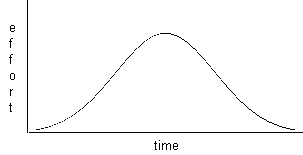
Figure 21.4
Now getting PGF to superimpose them gives the following kind of
picture:
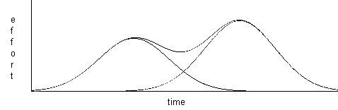
Figure 21.5
The outer "envelope" then shows the total cumulative loading for the
two
projects. With a relatively large number of projects, you can adjust
things
so that the top line is flat most of the time. "Flat projects"
(projects
which had a constant loading over their whole lifetime) could be used
to
handle things like vacations, education, overhead, etc. All dates were
constrained to business days, and once they were all calculated,
individual
project dates could be modified as desired.
Technically, this project was interesting because of the languages
and
software involved. It was also a decision assist type application. You
would get a screen just full of generated dates, and then, depending on
which dates were changed, it would do intelligent things with them.
This
meant that it was very important for the Screen Manager to report on
which
fields had been modified. All the calculations were done in REXX. Date
displays were handled by means of date input and output routines
written
in Assembler, driven by the Screen Manager using descriptors, so REXX
only
saw dates in canonical form (number of days from a reference date). If
you pick your reference date correctly, then day of the week is just
"date
modulo 7", and you can make Sunday 0, Monday 1, and so forth up to 6
(Saturday).
This system was used intensively over a short period to help reorganize
a portion of our division.
I am going to mention briefly another use I made of the Screen
Manager
because, although it was not a complete project, I found it very
suggestive
of the shape of user workbenches to come. Most of the application
development
on IBM hosts is done today (1993) using ISPF/PDF on TSO or CMS EXECs.
Within
this kind of workbench, developers use quite a wide range of
"languages":
HLLs, Assembler, JCL, DBDs, PSBs, MFS, FBP networks (hopefully!), 4GLs,
and of course documentation in his or her own national language. All of
these are held in different data sets, and have different, although
standard,
processing applied to them. PDF follows the "action/object" paradigm:
decide
the action, then select the object. Having to choose the action first
means
that you always have to know what language the thing you are working on
was written in. Also, in PDF you pick the same EDIT for everything, but
then usually have to go to a completely different menu to process the
text
you have entered, and you always have to reenter the object's name,
even
if you were working on it a few seconds ago! Native CMS is a little
different
since it is command-oriented, but here you have to remember the command
name to do the desired processing. Of course both lists support lists
with
optional "wildcards", but it is still hard to move a single object
through
a series of phases (like edit, compile, run test, etc.).
I figured that it would be nice if everything a developer was
working
on could be treated as an object of a particular type, with a unique
name.
The developer could just select the object she wanted to work on, and
the
system would know what language it was written in, and display an
action
bar showing what actions could be applied to it. So the interface would
prompt you for a component name (with optional "wildcards"), or you
could
ask for all components of a given type, and you could just click on an
entry in the action bar, without having to worry about choosing an
inappropriate
action for the object's type. Make the whole thing table-driven, and
you
have a very powerful, friendly system for application development - I
know,
because I built one for the CMS environment! All I had to do was select
the object, and an appropriate action bar would come up, which would
let
me select from a list of CMS EXECs (e.g. EDIT, COMPILE and the most
important
one of all: DESCRIBE). If the object types are user-modifiable, you can
be more specific, i.e. "Assembler source" could be split into
"programs"
and "macros", or you could have types like "screen", which will
generate
MFS or BMS, plus declares for the message layouts. You could drive
syntax-sensitive
editors for different languages, or for objects of type "diagram", you
could make the EDIT option call a picture editor. I also felt that each
action should go as far as possible, i.e. if you decide to COMPILE an
Assembler
source program, what you really want to do is translate it from human
format
to machine format - there is no particular point in making ASSEMBLE one
action and then LINKEDIT another. The COMPILE action could also
automatically
update control tables for use by tools like MAKE or symbolic debuggers.
The reason I said this prototype was suggestive is that, if you can
build this kind of development environment using FBP, and we know that
FBP also lends itself to building compilers and text processing
software,
this conjures up the very appealing image of a totally user-modifiable
development environment, built out of communicating standard
components.
This wouldn't be just a set of tools - this would let developers
continuously
expand and improve the workbench itself!
Last, but not least, in this rather varied set of examples, there
was
a project, which might be called an Electronic Information Booth, to
provide
a visitor to our building with information such as how to find people,
information about the building (layout, statistics, etc.), promotions
during
the month, a "trading post", and the cafeteria menu for the week.
Everything
was to be highly graphical and menu-driven. I prototyped this using the
same screen manager I described above and a User Response Analyzer to
implement
the paths between the screens. As I mentioned above, this screen
manager
had a fairly complete graphical specification facility based on
polygons,
so it was well suited to developing a lot of pictures in a hurry! Since
I already had the Screen Manager and User Response Analyzer, it was
really
just a matter of working with our very talented resident artist, Bob
White,
to develop the pictures. As it was around Thanksgiving, we decorated
the
Thanksgiving menu with a rather nice stylized corn-cob. During the
Christmas
season, we put the Christmas menu on its own screen with a little
Christmas
tree at the top! Later on, it was decided to implement this application
using PCs, but our prototype certainly played a significant role in
convincing
management of the validity of the idea.